Get Complete Project Material File(s) Now! »
ELASTIC DESIG
This chapter discusses the design of fixed-base gravity columns to stay elastic for the combination of axial compression and flexure, primarily focusing on square or rectangular HSS shapes because they are a common choice for one-story buildings. For the elastic design of these columns, the nominal axial compression strength, Pn, and the nominal flexural strength, Mn, are computed according to AISC 360-16 Chapter E and Chapter F, respectively. Then, the axial-flexure interaction equations in AISC 360-16 Chapter H are used. The boundary conditions are assumed as fixed at the base and pinned at the top with corresponding effective length factor, K=0.8. A design procedure is then proposed based on a single parameter that is found to control axial-flexure interaction. Finally, design charts are presented that can be useful to determine the adequate axial load ratio, α, given in the expected drift ratio, γ.
Evaluation of Column Stability
Axial Compression Strength, Pn
To determine the axial compression strength, Pn, the section needs to be classified as slender or nonslender using the width-to-thickness ratio (b/t or h/t). AISC 360-16 Table B4.1a. contains the limit of web and flange slenderness, λr, for compression members subject to axial compression that is the criteria to determine whether the section is prone to local buckling. These limits, given in Table 3-1, are based on material properties, the Young’s modulus, E, that is 29,000 ksi for steel and the specified minimum yield stress, Fy, that varies depending on the type of steel. Due to the fact that ry is smaller than rx for all HSS sections, the weak-axis (i.e., y-axis) will govern for flexural buckling, which is why the web and flange is reversely used for further calculation; now, h is the flange width and b is the web height. The limits of web and flange slenderness ratios, λp and λr, are obtained as Table 3-1, in which E is 29,000 ksi, and Fy is 50 ksi.
Flexural Strength, Mn
The moment capacity of columns, Mn is obtained according to AISC 360-16 Chapter F as described in Figure 3-2. Both web local buckling and flange local buckling need to be considered, however, it is unnecessary to consider lateral-torsional buckling (LTB) because of the fact that LTB does not occur in square section or section bending about their minor axis. Additionally, there are no slender webs in HSS, which can also be rechecked by comparing the width-thickness ratios with those limits presented in Table B4.1.a.
If the section is compact, meaning that it does not have any noncompact elements, Mn can reach the full plastic bending moment, Mp defined as FyZ, where Z is the plastic section modulus. If the section has noncompact flanges, Eq. (3-1) can be applied; if the section has noncompact webs, Eq. (3-2) can be used; if the section has slender flanges, Mn can be computed by multiplying Fy by the effective section modulus,
Axial-Bending Interaction
Since the axial force and bending moment are applied concurrently, the interaction formulas defined in AISC 360-16 Chapter H, Eq. (3-3) and Eq. (3-4) are used to evaluate the column stability. In these equations, the Pu term is the required axial compression strength, the Mu term is the required flexural strength, and the φ term is the strength reduction factor, 0.9.
Parameters to Vary and Alternative Interaction Equation
Two parameters are introduced to characterize the lateral displacement at the top of the column and the magnitude of the axial load: a story drift ratio, γ, and an axial load ratio, α. As shown in in Figure 1-2, at the top of the column, joists and joist girders can be installed in a way (the bottom chord can slide on the stabilizer plate) that does not restrain rotation and thus is typically considered pinned. The boundary conditions for this type of column is idealized as fixed base and pinned top, as illustrated in Figure 3-3 (a). The displacement at the top of the column, is characterized by the story drift ratio, γ, multiplied by the height of the column, as shown in Figure 3-3 (b). The column top forced to laterally move due to the story drifts made up of two components, as described by Eq. (3-5), the deformation of the vertical system, B, and the deformation of the diaphragm, D. In this section, the deflection is simplified as total story drift, , that might be imposed by seismic loading. However, the example in Chapter 6 will calculate B and D in accordance with the available literature such as FEMA P1026 (2015) and SDPWS.
The magnitude of the axial load is expressed as a normalized ratio of the required axial compression strength, Pu, to the design strength, ϕPn, as given in Eq. (3-6). The moment demand can be calculated as the axial force multiplied by the lateral displacement at the top of the column as given in Eq. (3-7), which is simplified into a function of the axial strength, height, story drift, and axial load ratio.
Substituting Eq. (3-6) and Eq. (3-7) into Eq. (3-3) results in Eq. (3-8). It is assumed that gravity columns will have an axial force that is greater than 0.2 times the axial strength, so Eq. (3-is not used. By rearranging Eq. (3-8) into Eq. (3-9), an alternative form of the interaction equation is proposed as a limit on the axial force ratio, α, given a lateral drift ratio, γ. In this equation, the limit on axial force is characterized by a single member specific parameter, Pnh/Mn, the reason of which will be discussed in the following section. Eq. (3-9) could be used to find the maximum drift a column can undergo if the axial force is specified, which will be verified in design examples in Chapter 6.3.3.
Proposed Design Procedure
Example Plots for Six Representative Hollow Square Sections
The use of Eq. (3-9) as a design tool is demonstrated by evaluating six example square tube columns with properties given in Table 3-2. The value of the left side in the interaction equation, Eq. (3-3), is plotted in Figure 3-4 for these six tubes with respect to the possible range of story drift ratios up to 3%, given in the axial load ratio, α, which is equal to 0.3 through 1.0. For the portions of the lines above the critical value of unity, it implies that the column section is not adequate under given combined loading conditions. In other words, the horizontal axis shows the acceptable story drifts columns can remain elastically stable as they are subjected to given gravity loads. From these plots, the following observations are made:
1.Figure 3-4 shows that tubes with the same outside dimensions that have a thinner wall have a higher value of the interaction equation. The value of the parameter, Pnh/Mn, is larger for thinner sections making them more prone to failure when subjected to lateral drift.
2.The outside dimensions of a tube are not an effective indicator of the maximum lateral drift a column can sustain before the interaction equation is violated. As shown in Figure 3-4, the different tube sizes are interspersed.
3.When α is less than 0.3, all columns stay safe, however, some sections begin to fail at α greater than 0.3. It can be concluded that tube columns may fail with relatively small compressive forces, if they are subjected to large drift.
Key Design Parameter,
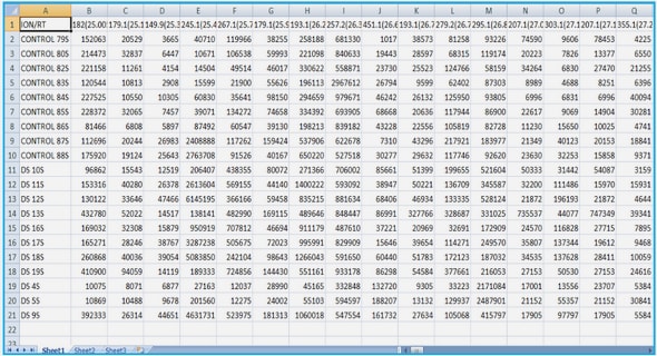
The suitability of Pnh/Mn as an indicator for HSS column stability during lateral drift is examined by evaluating all 388 rectangular or square HSS sections in Figure 3-5. All sections are categorized into six groups depending on a value of Pnh/Mn for the HSS cross section. The plots show that the interaction equation value is directly tied to the value of Pnh/Mn, in which the larger Pnh/Mn the HSS column has, the higher value of interaction equation it has. It is shown that the parameter, Pnh/Mn, is effective at predicting whether a section is more or less vulnerable to reaching the interaction limit state, as lateral drift is increased.
Also, all HSS square sections are tabulated in Table 3-3 in terms of Pnh/Mn. These data are consistent with the previous observation that the section with a high value of Pnh/Mn is likely to be slender and locally buckle before reaching the yield stresses, resulting in the column’s instability. Table 3-3 is useful for designing HSS square section columns subjected to moments induced by story drifts combined with axial compressive loads, which will be further discussed in the next section.
Developed a Simple Design Procedure
Based on the modified interaction equation, Eq. (3-8), and the proposed design parameter, Pnh/Mn, a simple design procedure is developed to determine the maximum allowable lateral drift that a tube gravity column can resist. First, it is necessary to calculate the value of Pnh/Mn, for the trial column size, which can be obtained from Table 3-3. Then, either Eq. (3-9) or the design charts given in Figure 3-6 can be used to determine whether the axial load ratio, α, is adequate for the amount of drift, γ, that is expected. An example application of this procedure for designing an HSS column will be presented in Chapter 6.
PLASTIC DESIGN
This chapter proposes three equations for highly ductile slenderness limits for HSS columns subjected to axial forces and large story drifts. The first is based on available analytical studies in the literature (Lignos and Krawinkler, 2010;2012). Through a finite element (FE) modeling, three new slenderness limit equations will be developed. For this study, six hollow-structural section columns will be modeled using Abaqus and validated against tests by Kurata (2004; 2005). Using the validated modeling approach, parametric FE studies will be performed to derive the highly ductile slenderness limits of HSS columns.
Proposed HSS Slenderness Limit Based on the Literature
As mentioned in Chapter 2, Lignos and Krawinkler (2012) proposed Eq. (2-10) for predicting the plastic rotation before reaching peak strength of an HSS section as a function of the width-to-thickness ratio (B/t) and the axial load ratio (P/Py). In typical bare steel moment connection tests, specimens typically reach their maximum moment strength at a story drift of approximately 0.03 rad before local buckling causes strength degradation (Engelhardt et al., 1998). Taking into consideration that the elastic rotation is approximately 0.01 rad, the plastic rotation before reaching peak strength is therefore approximately 0.02 rad. Substituting θp=0.02 in Eq. (2-10), and assuming a typical expected yield stress ratio, Ry=1.1 and the modulus of elasticity, E=29,000 ksi, the equation can be reformulated into the one which is about B/t. Note that B is the width of the outer dimension, b is the clear distance between web minus a corner radius. Thus, by taking the average ratio of b/t to B/t as 0.8 for square or rectangular HSS, a proposed slenderness limit is obtained as given in Eq. (4-1). This slenderness limit is expressed as a function of the axial load ratio with a lower bound, i.e., the current highly ductile slenderness limit in AISC 341-16.
Figure 4-1 shows a comparison of the existing width-to-thickness ratio limits in AISC 341-16 and the proposed highly ductile slenderness limits that is expected to allow a stable plastic hinge to form. The slenderness limits for a highly ductile member presented in AISC 341-16 Table D1.1 are Eq. (4-2), Eq. (4-3), and Eq. (4-4) for an HSS section, a wide-flange section with small axial load, and a wide-flange section with large axial load, respectively. Also, the slenderness limits proposed by Wu et al. (2018) are shown for wide flange sections that are interior columns subjected to constant axial loads as given by Eq. (2-7). The slenderness limits for HSS sections are referred to Eq. (4-1). All these four equations are plotted together in Figure 4-1, in which the horizontal axis is the axial load ratio, α=P/Py.
The following observations are:
The highly ductile slenderness limit for wide flange shapes, i.e., Eq. (2-7) (Wu et al., 2018), limits the axial load ratio to a maximum of 0.5 and is more conservative than the existing highly ductile slenderness limits for axial load ratios greater than 0.3.
The slenderness limit for tubes proposed in Eq. (4-1) is shown to be more conservative than the current highly ductile slenderness limit for axial load ratios greater than 0.4. The proposed slenderness limit approaches zero as the axial load ratio approaches 1.0.
Finite Element Modeling
In this section, a finite element modeling and analysis will be first performed to validate the models against experimental data on tube columns subjected to large axial force and concurrent lateral drift. Then, a parametric study will be conducted on 144 tube section columns. Based on the result from the finite element models, three new proposed slenderness limits for highly ductile tube sections will be developed through multivariate regression analysis. At the end of the chapter, the proposed limits will be compared and evaluated.
1. INTRODUCTION
1.1. Background
1.2. Research Motivation
1.3. Objective and Scope of Research
1.4. Thesis Organization
2. LITERATURE REVIEW
2.1. Story Drifts in One-Story Buildings
2.2. Designing for Diaphragm Deflection
2.3. Evaluating Fixity at Column Base
2.4. Elastic Design for Fixed-Base Columns
2.5. Plastic Hinge Design for Fixed-Base Columns
3. ELASTIC DESIGN
3.1. Evaluation of Column Stability
3.2. Parameters to Vary and Alternative Interaction Equation
3.3. Proposed Design Procedure
4. PLASTIC DESIGN
4.1. Proposed HSS Slenderness Limit Based on the Literature
4.2. Finite Element Modeling
4.3. Parametric Study
4.4 Developed Highly Ductile Slenderness Limits for HSS Columns
5. PINNED-BASE DESIGN
6. DESIGN EXAMPLE
6.1. Prototype Building
6.2. Drift Calculation
6.3. Required Axial Strength Calculation
6.4. Design Method 1: Elastic Design
6.5. Design Method 2: Plastic Hinge Design
6.6. Design Method 3: Pinned Base Design
6.7. Discussion
7. CONCLUSIONS
7.1 Elastic Design Method
7.2 Plastic Hinge Design Method
7.3 Pinned-base Design Method
7.4 Recommendations for Future Work
GET THE COMPLETE PROJECT
Design of One-Story Hollow Structural Section (HSS) Columns Subjected to Large Seismic Drift