Get Complete Project Material File(s) Now! »
MultiforITS-hop Vehicular Communication
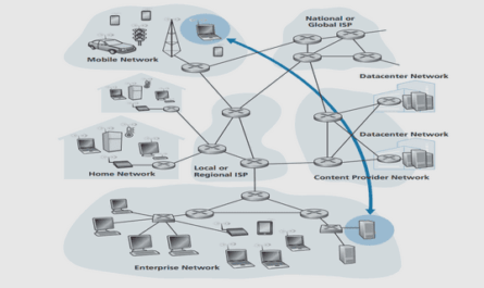
The term vehicular communication is not limited to communication between vehicles, but also involves communication with fixed units on the road, known as Road Side Units (RSUs), and with infrastructures connected to the Internet. This type of commu-nication are collectively referred to as V2X communication (see figure 2.1). The Car-to-Car Communication Consortium (C2C-CC) [90], proposed requirements for traffic efficiency applications where a pre-requisite is the necessity to have vehicle-to-vehicle communication involving support from the road-side units (RSUs) [91]. Thus vehicles communicating with RSUs form an integral part of the vehicular network communica-tion.
A vehicle can communicate wirelessly with another vehicle using radio waves. The communication may be direct or indirect. Vehicles within radio coverage of each other can communicate directly. A receiving vehicle is said to be in the radio coverage of a sending vehicle , if the receiving vehicle is able to correctly decode the transmitted signal from the sending vehicle. A sending vehicle can be an originator of a message or a forwarder of that message.
In a vehicular network, a source and a destination node may not be situated in the radio coverage of each other. Thus, a direct communication between them is not always possible. To enable in-direct « multi-hop” communication, intermediate nodes serve as relays to pass messages between source and destination. Different communication protocols designate, in different ways, the selection of intermediate nodes. This chapter gives an overview of existing multi-hop communication protocols that can be applied for vehicular communication in order to expand the ITS areas described in section 1.3. For consistency of description, in this chapter and the following ones, each vehicle or road-side unit in the network shall be denoted by “node”.
Wireless communication can be done using a number of modes such as radio, laser, inductive and capacitive coupling or sound . Radio waves provide a classical form of wireless communication, since they do not require a free line of sight, and communication.
over Radio Range medium ranges can be implemented.
Radio range of a wireless system is controlled by several key factors, and the driving factor among them is “transmission power”. The more energy put into a signal, the farther it can travel. The relationship between power output and distance traveled is a polynomial with an exponent of between 3 and 4 (non-line of sight propagation) [92]. So to transmit twice as far, 8 to 16 times as much energy must be emitted. Other factors that determine range include sensitivity of the receiver, gain and efficiency of the antenna and the channel encoding mechanism.
Antennas can be designed with directional preference. Many antennas are omni-directional, which means they can send and receive from any direction. For a given input power, directional antenna can reach farther with a clearer signal. Depending on ITS appli-cations, an appropriate antenna can be selected e.g., an RSU placed in a highway with directional antenna can disseminate traffic info messages related to all vehicles moving, in one particular direction, towards the RSU.
Several studi have shown that r dio range varies significantly in different directions and the perc ntage of asymmetric links in a network depends on average distance between nodes. Thus the comm nica ion ranges and physical locations of individual nodes.
Causes of define the connectivity Radio of ne work.
Irregularity
Radio irregularity is a common and non-negligible phenomenon in wireless networks [93]- caused mainly by devices and propagation media.
Device factors include antenna type (directional or omni-directional), transmitting power, antenna gains (at both transmitter and receiver), receiver sensitivity, receiver threshold and the Signal-to-Noise Ratio (SNR). SNR [94] is a measure to quantify how much a received signal has been corrupted by noise. It is defined as the ratio of signal power to the noise power corrupting the signal.
Media factors include media type, background noise and some other environmental 2factors,.1.3ImpactofsuchastemperatureRadioIrregularityandobsacles within a propagation media.
A radio wave is unguided (absence of solid medium to guide the wave between sender and receiver) – and a signal between a sender vehicle and a receiver encounters multiple mobile and reflecting objects, resulting in degradation of strength and quality of the signal received by a vehicle. This characteristic of the variation of signal strength at the receiver is known as “Fading” [95].
A radio signal can also take more than one path, depending upon objects present be-tween a sender and the receiver. Different paths have different length and signals will be received with different delays. These delayed signals may cause a destructive or constructive interference at a receiving vehicle. Causes of multiple path include:
• Reflection and refraction from water bodies and terrestrial objects such as moun-tains and buildings.
• Scattering by small objects cause multiple reflections of the signal, e.g. sign boards.
• DiffractionInterferencedue toComputationsharpedges c using signal splitting.
Other sources of signal degrad are: noise – signal alteration due to effects in transmitter a d receiver lectronics, nd interference – signal distortion due to superimposition with oth signals causing sig al impairment. Vehicular network protocol design must be able to take into account the seand bad Signal wireless Reception proagation conditions.
A radio receiver tuned to a particular frequency channel will receive whatever is trans-mitted on that channel plus any other signal received on that channel plus any back-ground noise [96]. If the strength of a transmission is significantly stronger than the noise, then the receiver is able to effectively ignore the noise – the transmission (nor-mally called the “signal”) has a good-signal-to-noise ratio. If a signal is of equal strength as the background noise, the receiver will not be able to discriminate the signal from the noise – resulting in a poor-signal-to-noise ratio or SNR [95]. For a given SNR value, two signal reception models are commonly used in order to estimate successful signal recep-tion [97]: SNR threshold based and Bit Error Rate (BER) based models. SNR threshold based m del uses the SNR value directly by comparing itNetworkwihanSNR threshold, and accepts only signals whose SNR values have been above thr shold at any time during the reception. BER based model probabilistically decides wh her not each set of bits (frame) is received suc essfully ba ed on the set length and the BER deduced by SNR 2and.2 modulation Node Characteristics [94] scheme used at in a the transceiver Vehicular.
Vehicular Networks are an emerging category of wireless network due certain partic-ularities of the nodes in the network. These particularities are to be considered for an effective local dissemination within a geographic area of an ITS event. A detailed de-scription of the node properties in a vehicular network is presented by Schoch et. al. in [98]. They are briefly described below (sections 2.2.1, 2.2.2, 2.2.3, 2.2.4), with the purpose of identifying their essential features and exploiting them for efficiently dis-seminating ITS events within a geographic area.
Node Speed
Nodes either denote vehicles or roadside units (RSUs) and their velocities may range from zero for stationary RSUs or when vehicles are stuck in a traffic jam to over 200 km/h on some highways [99] in Germany. For multi-hop message dissemination, the short enc unters between two nodes can lead to message loss during transmission. For example, a vehicle performing map updates via an RSU on a highway can leave the communication coverage of RSU before the update can complete. With the presence of intermediate vehicles, a vehicle can continue to perform map updates with the RSU, until Node it is complete Mobility. Pattern Typically the movement of vehicles are restricted by the road topology. Roads are con-structed to allow vehicles to move in both directions. At intersections and roundabouts, according to the destination, a vehicle can move arbitrarily, making driving direction of the vehicles unpredictable. This, for example, is the case at intersections and round-abouts. Roads can be distinguished into three types:
• City roads: Inside cities, the number of roads is relatively high. There are lots of smaller roads, but also bigger, arterial roads [98]. Many intersections cut road segments into smaller proportions. Often, buildings right beside the roads limit radio propagation.
• Rural roads: These roads usually have much larger segments, which means that intersections are more rare than in cities. Traffic conditions often do not allow the formation of a connected vehicular network, because too few vehicles are on the road. The overall direction of rural roads changes more frequently than the direction of highways.
• Highways: Highways are generally large and multi-laned, with well defined ex-its and on-ramps. Movements are quasi one-dimensional, and highways usually
keep their direction towards another city. Thus node mobility pattern on high ways Node Density is typically limited to inter-city movement.
Apart from speed and mobility pattern, node density is another key property of vehic-ular network. In mutual radio range, the number of other vehicles can vary from zero to dozens or even hundreds. In case of absence of nodes within mutual radio coverage of a node, immediate message forwarding becomes impossible, in order to reach nodes further down the road. In such situation, a node can store an event and forward that after finding a node in its vicinity (by having a neighbor sensing mechanism) or period-ically broadcast it for a certain period of time (until it has quit the relevant geographic area of the event), in the absence of neighbor sensing mechanism. E.g., The presence of ice on a road warning can be stored and periodically broadcast by a vehicle, until the vehicle leaves the segment, to alert vehicles that are encountered before leaving the segment.
Node density is not nly limited to the type of road, but also to the time of day. During daytime, density of vehicles on highways or in cities is high enough for immediate forwarding. However, during night, few vehicles are around and thus may necessitate repeated
Node Heterogene ity broad casting of events during the night.
Different types of nodes participate in ITS. A basic distinction can be made between vehicles and RSUs. Vehicles can be further categorized as private vehicles, authority vehicles, road construction and maintenance vehicles [98]. Certain ITS services can be restricted to type of vehicle. For example, only an emergency vehicle should be able to issue warnings about its approach to the vehicles ahead in order to get way on the high-way. The situation is similar for RSUs. Depending on the capabilities of the road side units, nodes may simply emit data to the network or have complete ad hoc functional-ity, and thus may be used for forwarding like other vehicles. Moreover, infrastructural nodes may provide access to background networks (e.g., to inform a traffic operation
centerFloodingabutroad co ditions). In contrast to vehicles, RSUs have widely different ca-pabilities. Regarding applications, they do not possess the same sensors as a vehicle and do n t process messages for p esenta ion to the driver or to take actions with the vehicle. Also, unlike vehicles, these nodes are stationary and do not have relation to 2any.3particular dividual in Vehicular Networks orcompnies,soRSUsdo not need to protect their privacy.
The main goals of intelligent transportation systems are to improve road safety and traf-fic efficiency [28, 15]. Vehicles can be enabled to communicate wirelessly and thereby alert drivers of un-anticipated events in advance. To achieve traffic efficiency (depend-ing on the relevance of an ITS service e.g., traffic jam warning, green-light optimal speed advisory), dissemination of traffic event should occur within the specific geo-graphic area, taking into account the particularities presented in section 2.2.
The simplest approach to broadcast is using pure flooding, where every node that re-ceives a packet for the first time forwards it to its neighborhood. This manuscript fo-cuses on efficient selection of forwarders in order to have reduced redundant reception of packets in a network and thereby disseminate information to nodes over a vehicular network. The efficiency lies in selecting reduced number of forwarders and still cov-ering every node geographically within twice the transmission range of a sender. A sender node can be a source node or a forwarder node of an ITS event.
When efficiency is not considered, pure flooding is simple and reliably provides a total coverage of a network. However, in terms of efficiency, pure flooding causes redundant packet receptions. Redundant packet reception occurs, when two or more forwarders transmit a packet to a set of nodes, where at least one node belonging to the set, is covered in common by the forwarders’ mutual transmission range). This in-efficiency of pure flooding, in terms of redundant receptions, has caused different optimization methods to be employed [100, 88, 101, 83]. Notably Ni et al. [88] propose several schemes to reduce redundant reception. In addition, Williams et al. [102] present a comparison of different broadcasting schemes in wireless networks.
Several protocols depending on neighborhood information are proposed. These proto-cols assume to have periodic information about the presence of neighbors around, in order to update and maintain their neighbor table. With this neighbor table, the proto-cols attempt to reflect a state of their neighborhood, at any given instance in time, and thereby use that information to designate forwarders to disseminate the packet further. A notable example is the Multi-Point Relay [103] scheme. MPR extends the range of neighbor information to two-hop away neighbors. In MPR scheme, a node periodically exchanges the list of adjacent nodes with its neighbors so that each node can collect the information of two-hop away neighbors. Each node, based on the gathered informa-tion, selects the minimal subset of forwarding neighbors, which covers all neighbors within two-hop away. Each node piggybacks its chosen forwarding nodes (MPRNs) on the hello messages. A node re-broadcasts a flood packet if the sender chooses this node as a MPRN. Otherwise, this node does not relay the flood packet.
A large number of current protocols and algorithms are based on topological approach of (i) having a mechanism whereby the communications ability of the wireless multi hop network is reflected into a graph abstraction and (ii) employing adaptations of classic algorithms and protocols, in order to allow proper operation of these over a graph abstraction with a rapidly changing topology. Some examples include OLSR [86, 104], NHDP [105], and AODV [106].
An alternative way of managing a wireless multi- hop ad hoc network is to assume that a graph abstraction is unattainable at least, a graph abstraction whose topology remains valid for sufficiently long time to allow for an algorithm to converge and in its place assume that each node is able to identify its own geographic location infor-mation.ProbabilisticThismanuscript assumes such availability of location information of a node. A comprehensive st of sc emes [88, 102] that can exploit the availability of location informati n (see ections 2.3.1, 2.3.2 and 2.3.3). The schemes basically differ in how a node estim tes redundant reception and how it accumulates knowledge to assist in 2re.-3broadcasting.1 decisionMethods.
Table of contents :
1 Introduction to Intelligent Transport Systems
1.1 Present Developments Towards ITS
1.1.1 ITS in Japan
1.1.2 ITS in USA
1.1.3 ITS in Europe
1.2 Currently Available Technologies to assist ITS
1.2.1 Sign-based Communication
1.2.2 Satellite Communication
1.2.3 Terrestrial Radio Broadcast
1.2.4 Dedicated Short-Range Communications
1.2.5 Cellular Mobile Communication
1.2.6 Image Recognition
1.3 Enhancing ITS services using Vehicular Communication
1.4 Socio-Economic Impact of ITS-based Vehicular Communication
1.5 Broadcasting ITS events using Mobility Information of Vehicles
1.6 Summary
2 Multi-hop Vehicular Communication for ITS
2.1 Radio Characteristics of Vehicular Networks
2.1.1 Radio Range
2.1.2 Causes of Radio Irregularity
2.1.3 Impact of Radio Irregularity
2.1.4 Interference Computation and Signal Reception
2.2 Node Characteristics in a Vehicular Network
2.2.1 Node Speed
2.2.2 Node Mobility Pattern
2.2.3 Node Density
2.2.4 Node Heterogeneity
2.3 Flooding in Vehicular Networks
2.3.1 Probabilistic Methods
2.3.2 Counter-Based Methods
2.3.3 Coverage-Based Methods
2.4 Exploiting Location Information for Flooding in Vehicular Networks
2.5 Functional Requirements for ITS Event Dissemination Algorithms
2.6 Summary
3 Eficient Flooding in Vehicular Networks
3.1 Location Specific Forwarding
3.2 Backfire – Controlling Redundant Receptions
3.3 Dynamic Scheduling – Decreasing Delay
3.4 Controlling Event Dissemination Frequency – Reducing Bandwidth Utilization
3.5 Adaptive Backfire – Increasing Connectivity
3.6 Summary
4 MHVB Protocol Specication for Location-based Flooding
4.1 Packet Format
4.2 Configuration
4.3 Transmission of MHVB packet
4.3.1 Jitter
4.4 Processing MHVB packet
4.5 Determining Backfire
4.6 Triggering Dynamic Scheduling
4.7 Summary
5 ITS-Specic Quantitative Evaluation of Position-Based Broadcast Protocols
5.1 Mobility Scenarios
5.2 Chosen Protocols
5.3 Simulation Settings
5.4 Performance evaluation of MHVB protocol under ITS requirements
5.5 Impact of Defer Times on Packet Re-transmission
5.6 Packet Freshness
5.7 Performance of Individual Components of MHVB
5.7.1 Performance of Sectoral Backfire
5.7.2 Performance of Dynamic Scheduling
5.7.3 Impact of Varied Relative Speed between Lanes
5.7.4 Varied Application Requirements
5.8 Summary
6 Securing Position-based Vehicular Communication for Intelligent Transport Systems
6.1 Attack Possibilities on ITS event dissemination
6.1.1 Identity-based attacks
6.1.2 Attacks on ITS data validity
6.1.3 Mobility Data Manipulation
6.2 Analysis of Position-based Attack
6.3 Counter-measures
6.3.1 Detection and Fusion – Trust Evaluation
6.3.2 Trustworthiness Sensors
6.3.2.1 Basic-trust Sensor – Prior Trust
6.3.2.2 Reception Range Threshold
6.3.3 Trust Decision – Handling False Data
6.4 Summary
7 Conclusion
Bibliography