Get Complete Project Material File(s) Now! »
Brief Historical Development of PLC
Like most of the innovations where the necessity is the underlying reason of their existence, the need of better controlling, maintaining and protection of the electrical power grid were important drivers for the appearance of PLC. In fact, the ability to transmit the information across the same pair of wires as are used for electrical power distribution grid has long been a goal. The idea of PLC has a long history that started from the early 1900s, when the first patents were made in this area [7–10]. Since that date, utility companies around the world have been using this technology for remote metering and load control, using at first narrowband PLC solutions operating in low frequency band (from 9 to 140 kHz) that achieved data rates ranging from few hundred bps to a few kbps [11]. Since the 1920s, the carrier-frequency transmission of voice has begun over high-tension lines for the purpose of operations management, monitoring and limitation, and removal of failures [9]. Since the 1930s, the Ripple Carrier Signaling (RCS) has been used over the medium and low-voltage lines to control peak events at demand side by issuing control signals to switch off heavy duty appliances [9]. This solution has been quite successful, especially in Europe, so it has been extended to include other applications related to “home automation” that allow controlling various in-home devices like illumination, heating, elevator, and so on. Overall, several innovative schemes related to remote transmission over power lines were made from early 1900s to 1980s, mainly due to the enormous evolution of electronics. By the late 1980s and early 90s, sophisticated error control coding techniques were proposed and implemented in a PLC modem hardware [7].
The tremendous revolution of digital communications in the 1990s, combined with the evolution of internet and related services and the developments in electronics have played an important role in renewing and increasing the interest in PLC [7]. Indeed, the high cost of the traditional access networks, which represent approximately 50 % of the investments in the total network infrastructures [12], presented PLC as a serious alternative technology for telecommunication service delivery for the so-called “last mile” connectivity, denoted as “access PLC”, as the infrastructures already exist. Access PLC networks can be realized using the medium and low-voltage power lines that feed homes as transmission medium, and can be used as a Local Area Network (LAN). This last application of the PLC technology is referred to as indoor PLC. As a result, indoor broadband PLC appeared as a response to the growing need of high speed communications over power lines, which can achieve significant higher data rates compared to those offered by the narrowband PLC systems.
Despite the main advantages inherent in indoor broadband PLC technology, it faces a number of serious challenges related to the harsh nature of the power-line medium. These challenges have recently made this technology a hot topic in communication area. Since the late 1990s, an increased effort has been put into characterization of PLC channels [13]. As a result, an international symposium dedicated to PLC was established in 1997; this is the International Symposium on Power-Line Communications and its applications (ISPLC), which became an official conference of the Institute of Electrical and Electronics Engineers (IEEE) communication society in 2006 [2]. Moreover, more and more tracks on the subject of PLC have emerged in several well-known international electrical engineering conferences (e.g. global communication conference). Simultaneously, an increased attention has been put from both the industry and research community to develop specifications and a global standard for high-speed communication over the power cables. Nowadays, indoor broadband PLC are specified by the standards that will be discussed in Section 1.4.
An Overview on PLC Systems
PLC is a technique that allows the transfer of digital information through the classical power lines. It profits from the already installed power-line infrastructures for data com-munication purposes. After years of development, the technology to deliver high-speed data over the existing electric power distribution grid has emerged. This technology is referred to as broadband PLC which uses medium- and low-voltage power lines to provide telecom-munication services (data, Internet, telephone, fax, etc) to individual subscribers in homes or businesses. In fact, PLC technologies have exploited a wide available frequency band, which can be grouped according to the International Telecommunication Union (ITU) into ultra-narrow-, narrow- and broad-bands, and which will be discussed in Section 1.3.3. The principle of functioning of broadband PLC is based on modulating low-energy/high-frequency data signals to the alternating electric current and transmitting them through the same wire that carry the low frequency electricity to buildings. Data signals thus propagate over the electrical installations and can be received and decoded remotely.
As PLC uses the electrical installations as transmission medium, it is of interest to provide an overview of the electrical installation networks in terms of operation voltages of power lines. The electrical power systems can be divided into three voltage levels as illustrated in Figure 1.1:
• High voltage power-lines, with voltages in the range from 110 to 380 kV, form a long-distance electric energy transportation network. They serve for the long-distance trans-port of energy from the power station to the big customer, and are usually implemented in the form of three-phase current overhead lines.
• Medium voltage power-lines, with voltages in the range from 10 to 30 kV, bring electrical power into cities, towns, and villages. They can span distances from 5 to 25 km, and are realized as both overhead and underground networks.
• Low voltage power-lines, with voltages from 110 to 400 V, ensure the final distribution to customer premises over distances up to a few hundred meters. Low voltage networks are also implemented as both overhead in rural areas and underground in urban areas.
The three power-line levels are interconnected to each other by means of transformers, de-signed in such a way that the energy loss is as low as possible at the frequency (50 or 60 Hz).
Broadband PLC systems fall into two broad categories: in-home PLC systems and last-mile (or access PLC) systems (see Figure 1.1). Access PLC uses electrical transmission lines to deliver high-speed broadband services from service suppliers to homes and offices. On the other hand, in-home PLC applications occur within a single building (house, apartment block or office building) and use the power grid inside the building as a LAN. Initially, considerable attention has been given to the utilization of low-voltage distribution lines as a last-mile technology. However, strong competition from Digital Subscriber Lines (DSL) and cable services has discouraged the deployment of outdoor PLC systems in most developed countries. Paradoxically, this high penetration of DSL services has encouraged the emergence of indoor PLC. In the following, further details on the PLC access networks and in-home PLC networks will be provided.
PLC Access Networks
PLC access networks are low-voltage power supply networks used for data transmission for the last mile access. An example of the architecture of the PLC access network is depicted in Figure 1.1, which mainly consists of a transformer unit and a number of power supply cables that connect the end users to the low-voltage network. The transformer unit allows the interconnection of the low-voltage network with medium- and high-voltage networks. In order to be able to convey telecommunication data, PLC last mile access has to be connected to backbone telecommunication networks by the means of base/master stations that may provide several communication interfaces with various backbones technologies such as DSL, optical fiber networks, etc. The PLC subscribers are connected to the low-voltage network via an electrical power meter unit, denoted “M” in Figure 1.1 or plug to any in-home socket in the electrical network. In the first case, the subscribers within a house or a building are connected to the PLC modem using another communications technology such as DSL and wireless local area networks. In the second case, the in-home electrical installation are used as a LAN, which is referred to in-home PLC technology.
In-home PLC Networks
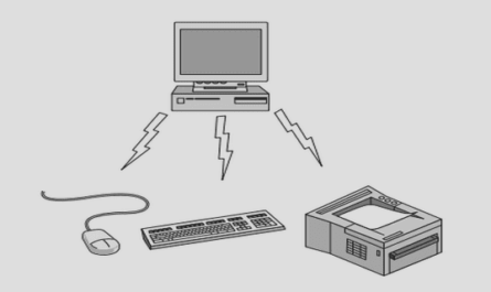
In-home PLC systems use the already existing electrical infrastructure inside a home as data transmission medium. In this way, the in-home backbone connecting all digital electronic devices within a private house (or flat) can be used as a PLC LAN. This exploitation enables new and highly convenient networking functioning without needing additional cables. Typical devices existing in private homes such as computers, high definition (HD) TVs, telephones, video devices, console games, printers, and so on can be connected and communicate via an access point to the PLC network. Nowadays, in-home PLC technology can be considered as one of the best solutions for providing home automation services like automatic light control, security observation and heating control [12].
A typical structure of an in-home PLC network is depicted in Figure 1.2. As can be seen from the figure, the network devices are connected via PLC modems, which are connected directly to the wall power supply sockets (outlets). In-home PLC networks can be connected to a PLC access network profiting from additional metering services such as remote meter reading and energy management. It can also be connected to any last mile access technology allowing the end users to profit from liberalized telecommunication market [12]. A gateway (see Figure 1.2) is used to separate between the in-home PLC network and the PLC access network avoiding problems related to the different natures of the two networks. In addition, it allows the communication between in-home PLC modems, and between the internal devices and the outdoor PLC network.
PLC Frequency Bands
As agreed upon by the ITU, the frequency bands can be represented as in Figure 1.3, where the band name abbreviations stand for super low, ultra low, very low, low, medium, high, very high, ultra high, super high, extremely high and tremendously high, respectively. PLC technologies, until now, have exploited a wide available frequency band to enable low-and high-speed data transmission over the power lines. They can be grouped into three categories according to the data transmission band as shown in Figure 1.3 [11, 13]:
1. Ultra Narrowband (UNB)-PLC technologies which offer very low data rate (<100 bps) in the ULF (0 3 − 3 kHz) band or in the upper part of the SLF (30 − 300 Hz) band. An historical example of UNB-PLC is the RCS. More recent examples are the automatic meter reading, turtle system and the Two-Way Automatic Communications System (TWACS).
2. Narrowband (NB)-PLC technologies operate in the VLF/LF/MF bands (3-500 kHz), which include the European comité européen de normalization (3−148 5 kHz) band, the U.S. federal communications commission (10− 490 kHz) band, the Japanese association of radio industries and businesses (10 − 450 kHz) band and the Chinese (3 − 500 kHz) band [13]. Two subgroups can be distinguished from NB-PLC technologies:
a) Low data rate: includes single carrier modulation-based technologies that offer data rates of a few kbps. Examples of these technologies are devices conforming to the following recommendations: International Organization for Standardization (ISO)/International Electrotechnical Commission (IEC) 14908-3 (also known as Lon-Works), IEC 61334-3-1, Insteon, X10, HomePlug C&C, SITRED, Ariane Controls etc.
b) High data rate: involves technologies that offer data rates ranging between tens of kbps and around 500 kbps. These technologies are today based on Orthogonal Frequency Division Multiplexing (OFDM). Typical examples of these technologies are those devices included in the family of the ongoing standard projects: Interna-tional Telecommunication Union – Telecommunication Standardization Sector (ITU-T G.hnem), IEEE 1901.2, Powerline Related Intelligent Metering Evolution (PRIME) and G3-PLC.
FIGURE 1.4: Overview of the UNB-, NB- and BB-PLC standards and specifications derived from [13].
with physical layer (PHY) data rates ranging from several Mbps to several hundred of Mbps. Typical examples BB-PLC technologies are devices conforming to the TIA-1113 (HomePlug 1.0), IEEE 1901, ITU-T G.hn (G.9960/G.9961), HomePlug AV2, Home-Plug Green PHY, Universal Powerline Association (UPA) Powermax, and Gigle Medi-aXtreme.
Many efforts have been made in order to standardize communications over power lines, notably by the IEEE and the ITU-T. An overview of the UNB-, NB- and BB-PLC standards and specifications is depicted in Figure 1.4 [13]. In the next section, we will give an overview of the latest standardization efforts in IEEE and ITU-T on broadband PLC, the context of our study.
Broadband PLC Specifications and Standards
With the growing interest in broadband communication over power lines, several indus-trial groups have been involved in the development and the standardization of broadband PLC products. In the last decade, broadband PLC chipsets came to the market are mainly based on specifications supported by consortia such as the HomePlug Powerline Alliance (HomePlug), the HomeGrid Forum, the UPA and the High-Definition Power-Line Commu-nication (HD-PLC) Alliance. The chips operate in the band from around 2 to 86 MHz, and in some cases, optionally up to 300 MHz, and allow data rates around 200 Mbits [13].
In order to ensure that the broadband PLC systems are widely successful, the IEEE and the ITU-T started work on such next-generation standards, namely the IEEE 1901 [14] and ITU-T G.hn [15], respectively. The HomePlug and the HomeGrid Forum played a significant role in the development of these standards. Next, we provide a brief summary of the major discussion groups and the proposed specifications, as well as the standards.
Table of contents :
Acronyms
Introduction
1 Broadband Indoor MIMO Power-Line Communications
1.1 Introduction
1.2 Brief Historical Development of PLC
1.3 An Overview on PLC Systems
1.3.1 PLC Access Networks
1.3.2 In-home PLC Networks
1.3.3 PLC Frequency Bands
1.4 Broadband PLC Specifications and Standards
1.5 MIMO for PLC
1.5.1 SISO PLC Channel
1.5.2 MIMO PLC Channel
1.6 Conclusion
2 Power-Line Channel and Noise: Characteristics and Modeling
2.1 Introduction
2.2 PLC Channel Characterization and Modeling
2.2.1 PLC Channel Characterization
2.2.2 PLC Channel Modeling
2.2.3 MIMO-PLC Channel Modeling
2.3 Noise Characterization and Modeling
2.3.1 Noise Characteristics
2.3.2 Noise Modeling
2.4 Conclusion
3 A MIMO Random Channel Generator for Indoor Broadband PLC
3.1 Introduction
3.2 Literature Overview and Proposal
3.3 MIMO-PLC Random Channel Generator
3.3.1 SISO PLC Channel Model
3.3.2 Extension to a MIMO PLC Channel Model
3.3.3 Strategy for Choosing an Offset Range for Each Channel Class
3.4 Results and Validation of the Model
3.4.1 Spatial Correlation of the Model
3.4.2 MIMO Channel Transfer Function Model
3.5 Conclusion
4 An Outage Capacity Approach for OFDM Systems Affected by Impulsive Noise
4.1 Introduction
4.2 Impulsive Noise in OFDM PLC: Illustration of its Detrimental Effect
4.2.1 Impact of Impulsive Noise Parameters on BER Performance
4.2.2 Impulsive Noise Mitigation Methods
4.3 Motivations and Proposal
4.4 Outage Capacity Approach
4.5 Schematic Representation of the Proposed Approach
4.6 Proposed Outage Capacity Approach for OFDM Systems
4.6.1 Channel Capacity in the Presence of Only Background Noise
4.6.2 Channel Capacity in the Presence of Impulsive Noise
4.6.3 Proposed Outage Capacity Approach
4.6.4 Proposed Outage Capacity Approach for PLC
4.7 Proposed Approach for Optimizing the Average Data Rate
4.8 Conclusion
Conclusion
List of Publications
A Impulsive Noise-Affected Symbol Outage Probability (ε) Integration
B Numerical Calculation of ε
C An Algorithm for Computing the Capacity of PLC Channels
D Study of the Function
Bibliography