Get Complete Project Material File(s) Now! »
Historical Background
First deployments of wireless networks on the world dates back to the 1920s. These systems used one big base station operating on the whole allocated spectrum to provide the service coverage for a city-wide area. Due to the interference constraint, the network was only able to handle a small number of simultaneous calls over a wide geographic region. As a result, the wireless phone call was a really luxury service. In addition, the long distance between a user to the base station was also a constraint. It required high transmission power of the user’s device, and resulted in quick drain of the device battery.
The cellular network architecture was invented and eciently solved the above limitations. As we know, the distance-dependent pathloss is the dominant factor in the power attenuation of the transmitted signal, see Chapter 2. The interference can be reduced if two co-channel base stations are spatially separated enough. That is the logic behind cellular system concept invented in 1947 by Douglas H. Ring, an engineer of Bell Labs. In his memoranda [77], he suggested that the wireless network deployment should use a number of smaller base stations instead of only one big base station in order to provide a wide range mobile service. As such, each base station transmits with lower power and provides sucient service coverage in a radio cell. To reduce the interference, the allocated frequency spectrum should be reused among cells but not in adjacent cells as it is illustrated in Figure 3.1.
The promise behind the cellular network design is thus the frequency reuse between spatially separated base stations. But on the other hand, as it splits the coverage area into radio cells, it requires a system to handover the call automatically without interruption when the user moves across cells during a conversation. Until the early 1970s, Amos E. Joel Jr, a Bell Labs engineer, invented a concept for automatic call handover in mobile cellular networks [78]. The cellular concept and automatic call handover, as well as some other technical developments invented during this time formed the mobile cellular system as we know today.
Technical Description
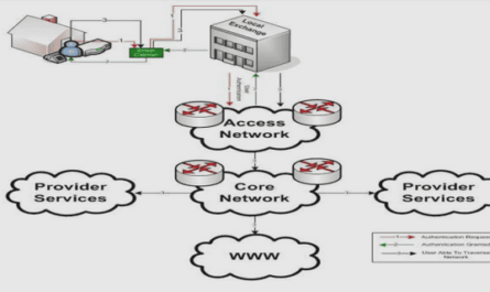
Like any communication network, the ultimate objective of the cellular network is to provide the end-user with reliable communication services. It is designed to have an abstract end-to-end architecture composed of a radio access network (RAN) and a core network as given in Figure 3.2. The core network provides all services to the end-users including connection to other networks, while the radio access network relays the communication channels between the end-user and the core network over the radio interface. RAN is implemented with the cellular concept that we have seen in x3.1. It is basically made up of base stations, and eventually other network elements depending on technology. The radio access network deals with all the characteristics of wireless communication while the core network is a wired-line network.
Protocol Architecture
We brie y describe the protocol architecture involving the radio interface. The control plane protocol stack is given in Fig 5.1.1.3-1 of 3GPP TS 23.401 [91], and it is shown in Figure 3.9. The Non-Access Stratum (NAS) protocol on the top of the control plane transports control signalling of MME to UEs. It is not visible to the eNodeB. The Radio Resource Control (RRC) provides the main controlling functions at the radio access interface (LTE-Uu). In addition, the Packet Data Convergence Protocol (PDCP) provides IP header compression (UP), encryption, and integrity protection (only for control plane) functions. The function of lower layers PHY, MAC, and RLC is as described in the reference model given in x3.2.3. The user plane is shown in Figure 3.10 taken from Fig 5.1.2.1-1 in 3GPP TS 23.401 [91]. It reuses the same transport level of the control plane for the radio interface. The similarity between the user plane and control plane highlights the fact that the whole system is designed as a at all-IP architecture (see, Holma and Toskala [89]). The user plane provides the user services through an IP tunnel established between UE and P-GW. Intermediate tunnels are established between relay nodes in the core network using a 3GPP-specic tunnelling protocol called the GPRS Tunnelling Protocol (GTP).
Table of contents :
Abstract
Acknowledgements
List of Figures
List of Tables
Abbreviations
Notation
1 Introduction
1.1 Bibliography
I Background and Assumption
2 Basics of Wireless Link Modelling
2.1 Radio Propagation Modelling
2.2 Interference and Noise
2.3 Signal Quality
2.4 Literature Review
2.5 Summary
3 Cellular Networks
3.1 Historical Background
3.2 Technical Description
3.2.1 Radio resource sharing
3.2.2 Cellular deployment
3.2.3 Protocol stack
3.3 Long Term Evolution (LTE) of UMTS
3.3.1 System Architecture
3.3.2 Protocol Architecture
3.3.3 Downlink Physical Layer
3.3.4 Radio Resource Control
3.3.5 Handover
3.3.6 Evolution to LTE-Advanced
3.4 Summary
4 Mobility Management in Cellular Networks
4.1 Mobile-Assisted Handover Measurement
4.2 Neighbour Cell List
4.3 Literature Review
4.3.1 Handover Optimisation
4.3.2 Handover Measurement
4.3.3 Neighbour Cell List Self-Optimisation
4.4 Summary
5 Mathematical Background
5.1 Modelling of Extreme Events
5.1.1 Heavy-Tailed Distribution and Regular Variation
5.1.2 Limit Laws of Sums
5.1.3 Limit Laws of Maxima
5.1.4 Limiting Joint Behaviour of Sum and Maximum
5.1.5 Application to Wireless Network Modelling
5.2 Stochastic Geometry
5.2.1 Point Processes
5.2.2 Shot Noise Field
5.2.3 Application to Wireless Link Modelling
5.3 Level Crossings of Stochastic Processes
5.3.1 Level Crossings of Stationary Gaussian Processes
5.3.2 Application to Mobile Radio Communication
5.4 Summary
6 System Model and Conventions
6.1 Stochastic Wireless Link
6.2 Spatial Distribution of Nodes
6.3 Extremes of Wireless Links
6.4 Set of Observed Nodes
6.5 Summary
II Wireless Link Modelling
7 Stochastic Geometry Modelling of Wireless Links
7.1 Introduction
7.2 Main Lemma
7.3 Joint Distribution of Interference and Maximum Signal Strength
7.3.1 Joint Distribution
7.3.2 Joint Density
7.4 Corollaries
7.4.1 Distribution of the Maximum Signal Strength
7.4.2 Distribution of the Interference
7.5 Distribution of the Best Signal Quality
7.6 Conclusion
8 Heavy-Tail Asymptotics of Wireless Links
8.1 Introduction
8.2 Tail-equivalent Distribution of Signal Strength
8.3 Asymptotic Distribution of Maximum Signal Strength
8.4 Asymptotic Distribution of the Interference
8.5 Asymptotic Joint Distribution of Interference and Maximum Signal Strength
8.6 Distribution of the Best Signal Quality
8.7 Conclusion
9 Some Properties of Level Crossings of a Stationary Process
9.1 Introduction
9.2 Excursions Above a Small Level
9.3 Crossings of Adjacent High Levels
9.3.1 Mean Number of Crossings of Successive Levels
9.3.2 Length of Excursions Above Successive Levels
9.3.3 Applications
9.4 Conclusion
III Mobility Management
10 Handover Measurement: Analysis and Applications to LTE
10.1 Introduction
10.2 System Description
10.3 Basic Formulation
10.3.1 Suitable Handover Target Found
10.3.2 Service Failure
10.3.3 Scanning Trigger
10.3.4 Scanning Withdrawal
10.4 Analytical Development
10.4.1 Probability of Finding a Suitable Cell
10.4.2 Probability of Service Failure P(failm)
10.4.3 Probability of Scanning Trigger P(trigm)
10.4.4 Probability of Scanning Withdrawal P(wdrawm)
10.5 State Diagram
10.6 Performance Metrics of HO Measurement
10.7 Application to LTE Handover Measurement
10.7.1 Evaluation Scenario
10.7.2 Result
10.8 Concluding Remarks
11 Autonomous Cell Scanning For Data Small Cell Networks
11.1 Introduction
11.2 Autonomous Cell Scanning
11.3 Network Assumption
11.4 Optimisation Problem
11.5 Result
11.6 Concluding Remarks
12 Neighbour Cell List Self-Optimisation
12.1 Introduction
12.2 Concept
12.3 Neighbour Cell List Self-Conguration
12.4 Neighbour Cell List Self-Optimisation
12.4.1 Neighbours Statistics Retrieval
12.4.2 Self-Optimisation Algorithm
12.5 Simulation
12.5.1 Performance
12.5.2 Convergence Speed of the Self-Optimisation Method
12.6 Conclusion
IV Appendices
A Probability
A.1 Characteristic Function and Uniqueness Property
A.2 Kullback-Leibler and Jensen-Shannon Divergences
B Resume Etendu
Bibliography