Get Complete Project Material File(s) Now! »
Coupled Approaches
In coupled systems, dierent aspects of the physical phenomena being modelled are treated separately. This may be for both physical and computational reasons, and can allow for detailed modelling of systems where a direct approach is not feasible. The extent of the coupling between models or `partitions’, can range from tightly coupled systems where a large amount of spatial and temporal information is shared with solvers using predictor and corrector steps in parallel or serial operations, to the sharing of more basic information, where data are generalised or simplied before being transferred. The classical approach to uid-structure type analysis extends to intrinsic coupling of the two partitioned elds57. This means that the numerical analyses communicate information at a level equivalent to the physical interface of the two partitions. Examples of this are given by Carstens et al.58 and Wuchner et al.59.
Utilising coupled modelling techniques for wind turbine wake analysis has been mentioned in literature60, although it is a relatively recent approach. Volund61 alluded to the work of Madsen where a BEM method was used in conjunction with a kinematic wake model. Thomsen62 demonstrated a method using a RANS ow solver of a wind turbine and wake to generate onset ow data for an aero-elastic simulation, however this method should be classied as a multi-tiered approach rather than fully coupled as the communication between the partitions is limited to one-way, and the solvers do not operate concurrently. Churcheld et al.63 presented a fully coupled method using an aero-elastic wind turbine simulation code and LES. This work is very similar to the methodology developed in this research and was submitted for publication soon after the journal manuscript by the author64. Both methods use the FAST aero-elastic simulator in conjunction with LES.
A common approach to coupling is a staggered approach also known as the conventional staggered solution (CSS) procedure57. In this process a prediction is made by one sub-system using either a previous time step value or an extrapolated estimate. The coupled sub-system then advances to the next time step with this value and passes information back to the other sub-system which can then advance to the current time step. This approach is a simple and eective way to implement coupling and is eective for coupled systems where one process is much less computationally demanding than the other process. This is the case for a system combining CFD and aero-elastic computation.
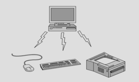
There are a number of options available for the way that the two coupled systems are controlled and the method in which they interact65. Partitioned systems which are developed alongside one another are often implemented as a single executable, or communicate directly with one another. Communication options for such coupled systems include shared memory, information piping and using message passing libraries. These techniques are areas of ongoing investigation in parallel computing and computational load balancing. Parallelisation of tasks and data operations in both the interface and the programs forms an important aspect of the system, especially for computationally demanding simulations. Strict time-stepping control is also important to robust operation, particularly for non-linear systems such as ow simulation.
Modelling the Wind Environment
Analysis of wind turbine operation and loading requires modelling of the dynamics of the wind turbine plant as well as the wind environment to which the turbine is responding. The latter presents several modelling challenges due to its transient nature and complex structure. Although a wind turbine operating in a steady onset ow is of interest, a more comprehensive analysis of a wind turbine design involves the examination of turbine responses to larger scale turbulence structures such as large gusts and rapid wind direction changes. A set of extreme wind events is presented in
the International Wind Turbine Design Standard IEC61400-1:200566. Variations in wind speed and direction can be modelled using techniques such as synthetic turbulence generation e.g. Mann67, where an inverse Fourier transform method is used to generate a set of turbulent uctuations with a specied shear, length scale, and intensity. This method can be applied to a computational uid dynamics (CFD) based simulation where a wind environment is modelled using a specied velocity
prole with the turbulent uctuations superimposed68. Introducing a large wavelength or amplitude turbulence structure is also possible using this method, however control over the resulting ow eld is limited due to the stochastic nature of the process.
An alternative is to model a wind event in a CFD simulation using a carefully constructed set of boundary conditions. This technique has been successfully implemented with LES by Norris et. al. 69,70 where a 3-D gust structure was modelled. This technique lends itself to the transient simulation of turbines in various wind conditions, however a wind turbine model capable of simulating the transient response of the turbine plant is required such as a coupled model.
1 Introduction
1.1 Wind Power
1.2 Wind Turbine and Wake Modelling
1.3 Modelling the Wind Environment
1.4 Turbine Modelling Limitations
1.5 Research Objectives
1.6 Thesis Outline
2 Theoretical Background
2.1 Aerodynamics of Horizontal-Axis Wind Turbines .
2.2 Computational Fluid Dynamics
2.3 Actuator Methods
2.4 Wind Turbine Design Standards
3 Methodology
3.1 Flow Solver
3.2 Aero-elastic Modelling .
3.3 System Coupling .
3.4 Actuator Methods
3.5 Flow Domain
3.6 Data acquisition and Analysis
3.7 The NREL 5MW Turbine
4 Single Wind Turbine Simulation
4.1 Actuator Model Comparisons
4.2 Validation
4.3 Single Turbine Wake
4.4 Summary
5 Multiple Wind Turbine Simulation
5.1 Simulation Parameters
5.2 Wake Structure
5.3 Turbine Array Performance
5.4 Turbine Loading and Control Utilisation .
5.5 Eects of Wake Meandering and Yaw Control
5.6 Summary
6 Transient Wind Conditions in a Wind Farm
6.1 Simulation Parameters
6.2 Wind Gust Propagating through a Turbine Array .
6.3 Wind Shift Propagating through a Turbine Array
6.4 Extreme Coherent Gust with Direction Change .
6.5 Damage Equivalent Loads
6.6 Summary
7 Discussion
8 Conclusions
References
GET THE COMPLETE PROJECT
Large Eddy Simulation of Dynamically Controlled Wind Turbine Arrays