Get Complete Project Material File(s) Now! »
Chapter 3 Calculations, Simulations, and Results
Launch & Parking Orbit
As stated in above chapters the Taurus XL rocket is used as the launch vehicle to constrain this mission. The Taurus XL rocket and launching from WFF will limit the initial inclination choices and the maximum altitude of the parking orbit. These limitations are discussed below in the Launch Constraints section. From the launch the spacecraft will coast into a circular parking orbit around the Earth. From this parking orbit the spacecraft will perform a burn into its transfer orbit. The timing of the burn is crucial to minimizing the total V of the mission.
Using a two-body analysis of the spacecraft and the Earth, the V required to push the spacecraft into the transfer orbit and capture around the Moon can be found. The speed and motion of the spacecraft is found around the Earth with the two-body problem, and the necessary speed to move into the transfer orbit is found by solving Lambert’s problem. The necessary speed to slow down around the Moon depends on the initial conditions of the transfer orbit and how the craft will enter the lunar sphere of influence. These calculations are done to show the importance of the positioning in the parking orbit when the burn is performed.
These basic calculations are not used for the transfer orbit or lunar orbit but are used to generate the contour plot shown in Figure (3.1). This figure shows the total V that the craft will have to be able to perform to push itself into the transfer orbit and then be captured around the Moon. The plot generated in Figure (3.1) shows the V requirements for a 400 km parking orbit launched on January 1st, 2015. As can be seen the values for the V can vary greatly and the timing of this burn is crucial to make sure this cost is not greater than the spacecraft’s budget. This contour plot also shows that if the lunar transfer orbit duration is important it can be improved by increasing the V . Because this mission does not depend on speed, taking the lowest V possible is advisable. Shown in Figure (3.2) is another contour plot generated for a 1000 km parking orbit launched on the same date January 1st, 2015. A launch like this would use a smaller spacecraft reaching the limits of the Taurus rocket’s range [7].
This code takes a user input of a desired launch date and processes a simple Earth-Moon model to the correct date. This model uses lunar ephemeris data for the Moon’s position in 2006 and then extrapolates the position of the Moon to a desired date [1]. The altitude of the parking orbit can be changed in the code to any value which should be constrained by the Taurus rocket. The launch is simulated as a simple Hohmann transfer from the surface of the Earth to the parking orbit altitude. This gives a simplified idea of the time the flight will take. The duration of in the parking orbit is stepped through in loops and used to find the position of the spacecraft. The code then uses loops to solve Lambert’s problem for the requirements and time of flight to the Moon. This Lambert’s problem solver takes in the position of the spacecraft and Moon as well as the desired time of flight. This analysis is not as accurate as the transfer orbit analysis that is done in the following sections, but still illustrates the point of the timing of the burn.
Launch Constraints
The launch constraints that the Taurus XL rocket gives are shown in Figures (3.3)-(3.6). Figure (3.3) shows the possible launch angles from three locations in the United States with WFF being one of them. This angle range is what limits the inclination angle of the parking orbit. Figures (3.4)-(3.6) show the maximum altitude for a given payload for different configurations of the Taurus rocket. The Taurus XL rocket is the 3110 configuration with the highest possible altitudes and payload masses. These figures give the constraints on the launch of the spacecraft [7].
Available Parking Orbit
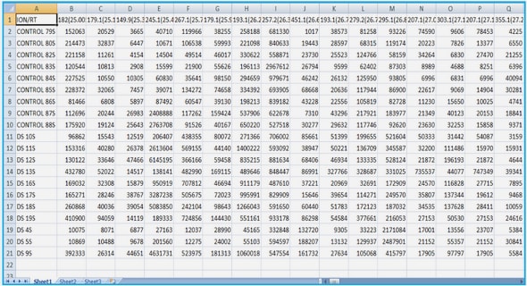
When launching from WFF the available parking orbits are restricted by the launch angle and vehicle. Looking at these available orbits they can be matched up to the necessary velocity to achieve any of the transfer orbits. Comparing the two gives the necessary V as discussed in Chapter 2. To do this comparison properly the velocities have to be expressed in the same Cartesian coordinates, so the available parking orbits should be listed with their position and velocities converted from the orbit elements. Some of these position and velocity numbers are listed in Tables (3.1) and (3.2). The first table shows the values for the parking orbits for an M0 of zero degrees, which would place it between the Earth and the Moon. This configuration can be seen in Figure (3.7) and explains why the y and z position data is all zeros, as well as the x-velocity data. The data shown in Table (3.2) is for a mean anomaly angle of 90 degrees. These tables were made using a series of nested loops in MATLAB to create a 4-D matrix. This matrix contains the (Semi-major Axis, Inclination, Mean Anomaly, Position or Velocity). The final entry in the matrix would have a magnitude of six, where the first three entries would be the x, y, or z position, and the final three entries would be the velocities. This can be visualized as a three-dimensional matrix where each element contains the position and velocity vector. The tables shown in Table (3.1) and (3.2) are slices of this three-dimensional matrix.
Parking Orbit Choice
As discussed above the parking orbit should be chosen so it closely matches the initial velocity requirements of the transfer orbit. This will minimize the required V to change into the transfer orbit. In the next section the transfer orbits will be discussed and this will show how these choices are significant. The possible inclination angles of the parking orbits from WFF are all out of range of the Moon’s orbit plane inclination, therefore any mission launched from WFF will not be able to make a simple planar orbit transition from the Earth to the Moon unless the spacecraft performs a plane change while orbiting the Earth. A plane change during Earth orbit is not advisable as the V requirements would be excessively high.
Transfer Orbit
One of the more heavily investigated parts of the mission is the transfer orbit. This portion of the mission involves the most variables and is analyzed with the most computer simulations to fully investigate the possibilities of a lunar mission from WFF. This section discusses these numerical simulations and shows plots of the trajectories that take the craft from the Earth to the Moon. As discussed in previous sections this analysis is done by solving the restricted three-body problem of the Earth-Moon-Spacecraft system. The spacecraft has a negligible mass and the Earth and Moon stay on circular orbits around their barycenter, remaining 180◦ apart from one another. The lunar orbital radius is constant and the Earth-Moon system is considered planar.
The Basic Trajectory – Planar
The first investigation into the transfer orbit is to consider a planar orbit from the Earth to the Moon, neglecting the z-axis. This basic trajectory is simulated using Newtonian,Lagrangian, and Hamiltonian dynamics. The results of this test showed nearly identical orbits for each case, which was to be expected, and these results are shown in Figures (3.8)-(3.10). The orbit shown is an hourglass trajectory similar to the Apollo missions to the Moon. This trajectory is used to show the more interesting dynamics of the three-body system, allowing the craft to depart the Earth and swing by the Moon. Performing the necessary burn at the Moon would allow for capture.
These simulations are performed in MATLAB and use the ode45 function to numerically integrate the equations of motion. In each case the integration is run for a time of seven days and given more strict tolerances than the standard function. The time is broken up into ten thousand equal time steps for the integration and the initial conditions for each case will be discussed in the sections below for each method. Using the defined time-steps keeps ode45 from creating jagged edges on the more simply performed portions of the orbit. From running these methods it is seen that the Lagrangian method is faster as explained in previous sections. The increased speed is because the Lagrangian method has fewer overall computations when the planet dynamics are removed from the simulation.
Newtonian
Because the motion of the planets is so simple it is easily maintained by using the right initial conditions and neglecting their more complicated equations of motion. Ignoring the planet’s equations of motion is not only done in the Newtonian method but all methods. The initial conditions for the simulation place the spacecraft at periselenium where it will be traveling in only the y-direction. This placement and direction of travel make the only variables for the initial conditions the initial velocity and the lunar miss distance. By integrating backwards the required Earth orbit departure velocity can be found and used to formulate the V required to get on this trajectory. The Earth and Moon start on the x-axis positioned at their respective points away from the barycenter. Using the equations of motion for the Newtonian system the trajectory is formed in Figure (3.8). The Earth is located near the origin and the Moon is located near the loop on the right.
1 Introduction
1.1 Lunar Mission Analysis
1.2 Reasons for Investigation
1.3 Previous Work
1.4 Orbital Mechanics
1.5 Thesis Layout .
2 Analytical Methods
2.1 Available Methods
2.2 Methods Used
3 Calculations, Simulations, and Results
3.1 Launch & Parking Orbit
3.2 Transfer Orbit
3.3 Lunar Orbit
4 Applications
4.1 Overall Application
4.2 Future WFF Projects
4.3 Senior Design Projects
4.4 Virginia Tech Spacecraft .
5 Future Work
5.1 Specific Spacecraft Influences
5.2 Desired Mission Constraints
6 Conclusions
6.1 Purpose
6.2 Findings
Bibliography
GET THE COMPLETE PROJECT
Lunar Mission Analysis for a Wallops Flight Facility Launch