Get Complete Project Material File(s) Now! »
Overview of the cable reception
Competition among cable operators and Telco providers is not only to provide the best networks that are capable of providing the highest data rates, but also to ensure the ability to receive huge amount of data in customer’s premises equipments, at low cost and low power consumption.
Since increasing the signal quality over the cable networks is not cost-effective, increasing the data rate translates into increasing the signal bandwidth, which is implemented by transmitting several bonded RF channels. There is a wish for providing 1 Gbps per home, which necessitates the simultaneous reception of 24 RF channels.
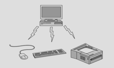
The trend for nomadic use of the information within a home, transforms the home receiver architecture from a distributed, STBs-based, to a centralized architecture (Fig 1), articulated around a home gateway. Data is re-distributed from the gateway to clients, using either WLAN (Wifi), MoCA or PLC as a communication pipe.
In addition, this highly-digitized architecture has several advantages over the mixer-based silicon tuners:
Agility: allows for a completely flexible plan for the cable operators
No RF mixer: no image rejection a harmonic rejection issues.
No group delay variation: digital channel selection can be realized with linear-phase filters (FIR).
Scalability: increasing the number of channels can be made without re-designing the RF & analog front-end.
Only re-scaling the digital channel selection block is required.
Down-stream cable test conditions
The following test conditions (Table 3 & Fig 7) are practically used by cable operators to assess the robustness of receivers. They are the heritage of a strong know-how, and deep analysis of worst-case field tests. They are used extensively though this document for specifying the receiver in order to get the right level of performance. They put more constraints on the receiver than the specified conditions provided in the previous section.
System-level design strategy for cable reception
Cable is an application where a large number of channels (~158) coexist on the same medium, using a FDD multiplexing technique. Hence, the ratio between wanted channel level and total input signal level is quite high. Since no aggressive RF filter can be used because the full cable band is being digitized, this leads to a highly challenging requirement on the ADC SNR.
However, the cable PSD is fairly flat, since differences in amplitude between the various channels are moderate (compared to wireless communication systems). This causes a flat non-linear distortion profile as well. In addition, the maximum input level can also been considered as medium (93 dBuV with CF=15 dB, which corresponds to a peak voltage of 0.3 Vpeak). Therefore, this leads to moderate non-linear distortion requirements on the RFFE & ADC. In addition, DSP techniques for equalizing time-interleaved errors and cancelling non-linear distortion errors are active research subject, while no techniques exist for cancelling broadband thermal noise. Because of this rationale, most of the impairment budget is allocated to the ADC noise. The impairment distribution is detailed in Table 5.
SNRin refers to the SNR limitation due to the cable transmitters and network, Es/N0 is the minimum required output receiver SNR, which allows a symbol demodulation with an acceptable BER.
Preserving as much room as possible for the RFFE+ADC noise, an implementation loss (IL) is allocated to each impairment.
RFFE+ADC+DCS noise (thermal, quantization, clipping).
RFFE+ADC non-linear distortion (2nd + 3rd order).
ADC time-interleaved mismatches (offsets, gain and time-skews).
PLL in-band, close-in and distant phase noise.
Noise analysis
Using the theory explained in the previous chapter, the Noise Figure, which is required by the receiver is calculated for the different test conditions (NFRX column in Table 6), at min/max levels and min/max frequencies.
The RFFE maximum voltage gain (GvRFFE column in Table 6), that ensures negligible clipping on the ADC, is calculated from the ADC full-scale and the total RF input level.
The next step is to make a first-order model about the RFFE noise figure: broadband tuners typically show a NF in the 3-6 dB range, at maximum gain. It is expected that our RFFE can be on the same NF range than broadband cable/terrestrial tuners. NF degradation, at low gain values, is also taken into account in our RFFE noise model (Fig 11), which is based on simulation of a 3-stage LNA cascade. RFFE NF model (NFRFFE column in Table 6) is 5 dB for gains above 30 dB, and increases with a 2nd order polynomial law up to 24 dB at 0 dB gain.
Table of contents :
Acknowledgments
Abstract
Synthèse
Contents
List of abbreviations and symbols
Introduction
CHAPTER 1. RF receiver architecture state-of-the-art
1.1 Mixing process
1.1.1 Image-reject filter
1.1.2 Image-reject mixers (IRM):
1.1.3 Mixing with LO harmonics
1.1.4 Harmonic-reject mixers (HRM)
1.2 Sampling process
1.2.1 Lowpass 1st order sampling
1.2.2 Bandpass 1st order sampling (sub-sampling)
1.2.3 Nth-order sampling
1.3 Analog-to-digital conversion
1.3.1 Flash
1.3.2 Pipeline
1.3.3 SAR
1.3.4 Delta-sigma
1.3.5 Time-interleaving
1.3.6 ADC state-of-the-art comparison & expected future trends
1.4 Continuous-time receivers
1.4.1 Super-heterodyne
1.4.2 Homodyne
1.4.3 Low-IF
1.4.4 Digital-IF receiver
1.5 Discrete-time receivers
1.5.1 Discrete-time analog-processing receivers
1.5.2 Hybrid-Filter Bank (HFB) receiver
1.5.3 Direct RF digitization receiver
1.5.3.1 Bandpass direct RF digitization receiver using filtering ADCs
1.5.3.2 Lowpass direct RF digitization receiver using Nyquist ADCs
1.5.3.3 Bandpass direct RF digitization receiver using Nyquist ADCs
1.5.4 Summary & work orientation
CHAPTER 2. System-level design framework for direct RF digitization receivers
2.1 System-level aspects
2.1.1 Signal characteristics
2.1.1.1 Signal distribution
2.1.2 BER and Es/N0
2.1.3 Sensitivity test
2.1.4 Adjacent & blocker test
2.1.5 Intermodulation & broadband non-linearity test
2.1.6 Summary
2.2 Receiver system-level design
2.2.1 Equivalent noise figure
2.2.2 Receiver implementation loss
2.2.3 Noise analysis
2.2.3.1 Quantization noise
2.2.3.2 ADC Thermal noise
2.2.3.3 Over-sampling ratio
2.2.3.4 ADC clipping noise and optimum loading factor
2.2.3.1 Impact of signal-dependent noise
2.2.3.2 ADC Noise Figure
2.2.3.3 RFFE gain range
2.2.3.4 Cascaded Noise & impact of RFFE gain flatness
2.2.3.5 Summary
2.2.4 Non-linear distortion
2.2.4.1 Non-linear distortion in a narrowband system
2.2.5 Non-linear distortion in a broadband system
2.2.5.1 Composite distortion products identification
2.2.5.2 Composite Triple Beat (CTB) link with 3rd order intercept point (IP3)
2.2.5.3 Composite Second Order (CSO) link with 2nd order intercept point (IP2)
2.2.5.4 Impact of RFFE gain & phase unbalance
2.2.5.5 Summary
2.2.6 Aliasing
2.2.7 Time-Interleaved ADC
2.2.7.1 Offset mismatch
2.2.7.2 DC gain mismatch
2.2.7.3 Sampling time skew
2.2.7.4 Transfer function mismatch
2.2.7.5 Statistical behavior of the channel mismatches
2.2.7.1 Summary
2.2.8 Sampling clock requirements
2.2.8.1 In-band Phase Noise
2.2.8.2 Reciprocal sampling
2.2.8.1 Summary
2.2.9 Digital channel selection
2.2.9.1 Quantization noise
2.2.9.1 Summary
CHAPTER 3. Application to the system design of a multi-channel cable receiver
3.1 Overview of the cable reception
3.2 Cable reception key specifications
3.2.1 Standardized requirements
3.2.2 Worst-case field test conditions
3.2.2.1 Down-stream cable test conditions
3.2.2.2 Coexistence with MoCA
3.3 System design of cable multi-channel receiver
3.3.1 ADC sampling rate
3.3.2 System-level design strategy for cable reception
3.3.3 Noise analysis
3.3.4 RF tilt equalizer impact on noise
3.3.5 RFFE Gain range
3.3.6 Non-linear distortion analysis
3.3.7 Anti-aliasing filter
3.3.7.1 Anti-aliasing filter specification
3.3.7.2 Anti-aliasing filter characteristics choice
3.3.8 Time-Interleaved ADC specification
3.3.8.1 TH Offset-mismatch specification
3.3.8.2 TH Gain-mismatch specification
3.3.8.3 TH time skew-mismatch & BW mismatch specification
3.3.9 Sampling clock specification
3.3.9.1 In-band phase noise
3.3.9.2 Close-in phase noise
3.3.9.3 Distant phase noise
3.3.9.4 Overall phase noise specification
3.4 Summary
CHAPTER 4. Realization & measurements
4.1 RF front-end
4.1.1 Low-noise amplifier
4.1.2 RF Tilt Equalizer Design
4.1.2.1 Capacitor and resistor arrays
4.1.3 Anti-Aliasing Filter
4.1.4 Single-To-Differential Converter
4.1.5 RFFE measurements
4.2 Mixed-signal front-end
4.2.1 ADC
4.2.2 Digital Channel Selection
4.2.2.1 Hierarchical band splitting
4.2.2.2 Digital Down-Converter
4.3 Mixed-signal AGC loop
4.3.1 RMS loop
4.3.2 Peak loop
4.4 RF tilt equalizer control loop
4.4.1 RFFE measurements
4.5 System-level simulations and measurements
4.6 Summary
Conclusions & perspectives
Publications and patents
References