Get Complete Project Material File(s) Now! »
Chapter 2 Code Development
Methodology
The calculation of the co-channel interference power in a receiver is crucial for a system designer. Along with the carrier-to-noise ratio (CNR), the calculation of all or any interference power received provides a highly useful performance measure: the overall carrier-to-noise-plus-interference ratio (CNIR), which includes the interference components as well. More commonly, and perhaps confusingly, it is referred to as the overall CNR, which simply includes the interference contributions as follows [3]:
Here, the overall carrier to interference ratio (C/I)O is calculated as follows [3]:
The subscripts CC and IM indicate co-channel and intermodulation interferences, respectively, which are the two most commonly calculated interferences for a system that employs frequency reuse as well as power amplifiers driven in the nonlinear region. The (C/I)O may include all types of interferences that need to be calculated. The subject of our discussion in this thesis is only co-channel interference. Therefore, the (C/I)O hereafter includes only co-channel interference as follows:
The downlink co-channel carrier-to-interference ratio (C/I)CC-DL is primarily a function of the reuse number and of the aggregate power due to the power in the sidelobes of interfering co-channel spot beams that is received in an earth station receiver. On the other hand, the uplink co-channel carrier-to-interference ratio (C/I)CC-UL is dependent upon the reuse number and the number of co-channel users transmitting simultaneously and received at the sidelobes of the interfered beam.
The equations above assume that a linear (bent-pipe) satellite transponder is being used. If a transponder is non-linear or has onboard processing (OBP), then the respective uplink and downlink CIR or CNIR are more useful than the overall CNIR. Furthermore, if Forward Error Correction (FEC) coding is used to combat errors, then the respective link Bit Error Ratios (BERs) will be more useful in determining the performance of the links.
By the use of digital modulation, OBP and FEC coding, one link will always be dominant in determining the performance of the system since BER for that link will dominate and exceed the BER of the other link. In such a case, an overall CNR or CNIR is of no importance; rather, the calculations for the respective link BERs are preferred. To arrive at the link BERs, the respective CNIRs are needed. This program makes no attempt to calculate the SNR or Eb/No of a system. It merely provides a tool to calculate the link CNRs, CIRs, and CNIRs.
The following sections first present assumptions made and a simplistic flowchart for the development of the computer code, followed by the details of the calculation methods used to calculate co-channel interference in the uplink and the downlink directions.
MATLAB, a software tool for high-level programming, has been used for the development, implementation and testing of the computer code used for calculating co-channel interference. The main code and its supporting user-defined functions are shown in Appendices B and C.
Assumptions
Several assumptions were made in the development of this analytical computer code. Following are most of the assumptions made:
I. A single satellite or elevated platform based spot beams provide the frequency reuse scenarios assumed.
II. Spot beams have a user-specified pattern illumination or beamwidth and provide overlapping coverage at X-dB level below the beam peak. The overlap, at least at the center of coverage, provides continuous coverage.
III. Beamwidths for all spot beams of a link are the same.
IV. The relative antenna patterns for all the spot beams of a link are the same.
V. Centers of spot beams follow an overall hexagonal pattern in the angular domain. This implies that the angle between any two adjacent spot beam centers, as seen from the satellite, is the same and that the spot beam centers are vertices of a hexagon, for which the lines joining the vertices or any two spot beam centers represent the angle, not distance, between the spot beam centers, as shown in Figure 2.4. This, along with the same beamwidth spot beams, implies that the cells that are formed at the edges of coverage would cover a larger surface area, as shown in Figure 2.5.
VI. For satellite signals the transmit power is the same for all spot beams.
VII. The source-signal transmit-power and antenna gain are same for the user and the interferers of a link. In other words, if the uplink user is a mobile, then the uplink interferers are mobiles with the same transmit power and antenna gain as the user mobile.
VIII. Separate antennas are used on the satellite for the uplink and the downlink.
IX. In the uplink, exactly one co-channel interferer is actively transmitting in each co-channel cell.
X. The calculations are for FDMA/TDMA systems, where the channel is allocated to one user at a time in any beam, and not for a CDMA system, where all users are sources of interference/noise.
XI. The location of a co-channel interferer is random, but worst-case and best-case locations are also investigated.
XII. No power control is used by any receiver or transmitter.
XIII. Antenna scan loss is taken into account, but it does not change the spot beam antenna patterns.
XIV. All interference signals including the system noise are statistically independent wide-sense stationary random processes of zero means. [4]
Flowchart
To understand how the code calculates co-channel interference for both the uplink and the downlink and the overall CNIR for the system, the program flow is illustrated through the multi-page flowchart in Figure 2.1 below. A more rigorous program flow, with more details, is given in Appendix A.
Input File for the Program
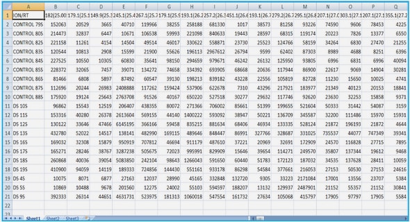
A Microsoft Excel file with three different worksheets for the General, Uplink and Downlink input parameters and their values is read by the code. An explanation of each of the worksheets follows. A sample General worksheet is shown in Table 2.1 below, which is taken from Appendix D.
This worksheet lets the user specify values for the parameters that fix the position of the satellite as well as the center of coverage. It is important to specify the center of coverage since a hexagonal tessellation, in the angular domain, is assumed for the coverage cells; in other words, the cells are packed together in a way that they overlap and a hypothetical line joining the centers of spot beams surrounding any given spot beam center forms a hexagon. The worksheet also allows the user flexibility in specifying a separate footprint for the uplink and the downlink. It also specifies the minimum elevation angle so that the code can ensure that user earth stations in both the uplink and downlink are able to see the satellite at or above this minimum elevation angle. The equations for the satellite visibility, taken from [3], are presented below. Refer to Figure 2.2 for the illustration of the angles used.
For the satellite to be visible to the earth station, the satellite can not be any lower than point T in Figure 2.2 above, which implies that:
Additionally, the satellite should be at an elevation greater than or equal to the minimum elevation angle specified in the input file. In our case, we assumed that the minimum elevation angle is 5 degrees. The elevation angle is given by [3],
Sample Uplink and Downlink worksheets are shown in Tables 2.2 and 2.3 below, which are also taken from Appendix D. They give the user of the program flexibility in using different values for differing uplink and downlink scenarios.
Appendices D and E provide verification of the calculations done by the computer code developed here. Appendix D uses input values that are from a sample problem given in [3]. Since no sample problem could be found that included the calculation of co-channel interference for a system with assumptions similar to those made here, Appendix E provides hand calculations for a simplistic case to verify and compare the CNR and CIR for both the uplink and the downlink.
Another added flexibility is that, for instance, the uplink user earth station’s location in Latitude and Longitude may not be known and it may be of interest to see what kind of interference may occur if the uplink earth station were at the fringe of a coverage cell, which may be in the outermost tier of coverage. So, the user locations for both the uplink and the downlink can either be entered as Latitude and Longitude in decimal degrees North and West, respectively, or be specified by selecting the locations on the respective uplink and downlink coverage maps.
By giving the user a choice to select whether all co-channel cells are used for calculations or only the cells in the first co-channel tier are used, the user can investigate the notion that the first tier of co-channel cells are usually the most dominant contributors. These worksheets also allow the user to input miscellaneous losses that belong solely to the user earth stations, along with miscellaneous losses that apply jointly to user earth stations and interferers. Scan Loss, which is the loss in gain of the satellite antenna for spot beams other than the one at the boresight of the antenna, is also considered. It is given by the following equation:
The satellite antenna pattern choices in the program are limited and the choice is only in the taper value for the type of illumination of a uniform circular pattern. The uniform circular pattern is given by the equation below. An increase in the taper value corresponds to a decrease in the sidelobe level of the pattern. Table 2.5 shows the effect of the different pattern tapers on the sidelobe levels [5]. The normalized antenna pattern with taper ‘tpr’ is given by,
Calculation of Uplink Co-Channel Interference
The main objective of this part of the code is to calculate the interference received by the satellite antenna from uplink users in the co-channel cells that use the same exact frequency as the main uplink user earth station or mobile. One noteworthy assumption for this link is that there’s one and only one user in each co-channel cell actively transmitting in the desired channel.
In order to calculate the total uplink co-channel interference power received by the satellite receiver, the code follows a 3-step process as shown below:
(1) It draws the coverage map and identifies the co-channel cells.
(2) It finds the angle the co-channel interferers make with the boresight of the uplink satellite antenna pattern for the spot beam that serves the uplink user earth station or mobile. It finds such interferers for three cases: (a) Randomly distributed interferers, (b) worst-case placement of interferers, and (c) best-case placement of interferers.
(3) It adds the contributions of these co-channel interferers to find the total interference power received by the uplink satellite receiver.
Step 1
After reading in different parameter values from the MS Excel input file, the code essentially draws the normalized antenna pattern of the satellite antenna based on the 3-dB beamwidth and the taper value specified by the user in the input file. It, simultaneously, calculates the angular radius of a spot beam based on the input value for the X dB point of overlap, which produces a tessellated cell distribution in the angular domain as depicted in Figure 2.4.
The X dB radius is calculated using an interpolation function in MATLAB, which uses the cubic spline method, since only discrete values can be calculated in MATLAB for the normalized antenna pattern for the given 3-dB beamwidth and pattern taper values specified in the input file. The code used to calculate the X dB radius and to plot the antenna pattern is a user-defined function called, ‘PLOT_ANT_PATTERN’, and is shown in Appendix C.
The spot beams are distributed in a way that any two adjacent spot beam centers on the hexagonal grid form the same angle anywhere on the coverage map. This method bypasses the labor of calculating the radius of different cells or finding the distance between co-channel cells on a curved earth surface; rather, it allows the use of the geometry depicted in Figure 2.4, which is similar to the geometry used for terrestrial cellular coverage except that the distances actually correspond to angles. This allows the spot beams to form footprints of any shape on earth. The footprint formed by a spot beam directly at the sub-satellite point is circular in shape, but the footprint formed at a slant angle would be somewhat elliptical in shape, as shown in Figure 2.5.
Following equations are used to find the angles between two adjacent cells, θac, and between two adjacent co-channel cells, θcc.
Step 2
In this step, the angle each interferer makes with the boresight of the uplink antenna’s spot beam, which serves the user earth station or mobile, is found along with the different path lengths they have from the satellite.
The angular separation of the co-channel cells is calculated using the same equations as in step 1, except that instead of using a cell reuse value of 1 to come up for the entire coverage map, the actual cell reuse value is used. Three different placement scenarios are considered for the interferers, namely, random, worst-case and best-case placements. For all cases, the assumption that exactly one interferer exists in each co-channel cell still stands.
For the random scenario, the interferers are randomly placed in the respective co-channel cells. This is done by the use of a built-in random number generator function in MATLAB. The interferers are randomly distributed in ‘ρ’, which appears to be the radius of a cell in the angular domain based coverage map, but is actually the angular separation between the interferer and the center of the spot beam. The value for ‘ρ’ varies between 0 and the X dB Beamwidth of the spot beam. The interferers are also randomly distributed in ‘φ’, which varies from 0˚ to 360˚.
For the worst-case scenario, an interferer is placed at a point within the cell at which the angular separation between it and the usercell’s center is such that the relative antenna pattern contribution is the maximum possible from the interferer’s cell. In most cases, the closer an interferer is to the usercell’s center, the more it can contribute towards the interference power since the relative antenna pattern value of the usercell’s spot beam is higher when close to the main lobe of the pattern.
For the best-case scenario, an interferer is placed at a point within the cell at which the angular separation between it and the usercell’s center is such that the relative antenna pattern contribution is the minimum possible from the interferer’s cell. Often times, this would show that the angles are such that they fall in or are close to the nulls in the antenna pattern.
The distribution of the cells in the angular domain, although simple, does require that the co-channel interferers and the user earth station or mobile be defined or mapped to the angular coverage map. The co-channel interferers are defined in the program in terms of angles on the angular coverage map. On the other hand, the earth station/mobile could be input one of two ways: 1) As Latitude and Longitude on the earth’s surface, or
2) As a point selected by the user on the angular coverage map created by the program. Therefore, the program maps the user location, if input as Lat/Long, to the angular coverage map. Since the co-channel interferers are on the earth surface and different distances apart from the satellite, the co-channel interferers’ locations on the angular coverage map need to be mapped to the earth’s surface.
All of this is accomplished by using a satellite-centric coordinate system with some convenient properties, by calculating a transformation matrix that can be used to transform coordinates between the earth-centric and satellite-centric coordinate systems, and by using a convenient mapping relationship between points on the angular coverage map and the satellite-centric coordinate system. Figure 2.5 shows the two coordinate systems.
In the earth-centric coordinate system, the positive y-axis points in the direction where the Longitude on the earth surface is 90˚ East, the positive x-axis points in the direction where the Longitude on the earth surface is 0˚, the x-y plane corresponds to the equatorial plane, and the positive z-axis points in the direction where the Latitude on the earth surface is 90˚ North. Whereas, in the satellite-centric coordinate system, the positive z′-axis points in the direction of the line vector from satellite to the center of coverage on the earth surface. For convenience and simplicity, the y′-axis is assumed to have no x-component (in the earth-centric system), and the cross product of these two axes produces the unit vector for the x′-axis
The equations used to define the satellite-centric coordinate system’s axes are shown below.
Since the y′-axis is assumed to have no x-component, it can be calculated in one of the following ways,
Therefore, the unit vector for the positive x′-axis is given by,
To convert a point in one coordinate system to the other, transformation and translation of axes is done. The equations used are as follows:
Here, the rows of the 3×3 transformation matrix, T, represent the direction cosines of the x′-axis, y′-axis and z′-axis, respectively, in the earth-centric coordinate system. The 3×1 translation matrix, t, represents the coordinates of the satellite in the earth-centric coordinate system.
Given that coordinates for all points in the earth-centric system can be transformed into coordinates in the satellite-centric system, a convenient mapping relationship between points on the angular coverage map and the satellite-centric system was used. Again for convenience, it is assumed that the angle that the projection of any point in the satellite-centric system on the x′ y′ plane makes with the x′-axis is the same as the angle the mapped point (on the angular coverage map) makes with the alpha-x-axis. How far the mapped point is from the center of the coverage map is simply the angle in degrees between it and the coverage center.
In order to calculate the distance between the satellite and the different interferers on the earth surface, a user-defined function called ‘DIST_SAT2EARTH’ is used. This in turn makes use of another user-defined function called ‘INTRSCTN_RAY2SPH’ to find the closest point of intersection between a ray and the spherical earth.
Step 3
Using the angles that the interferers make with the boresight of the usercell’s spot beam and the distances that the interferers are from the satellite, the relative pattern values of the interferers and their respective path losses are found. Equation 2.7 is used for the relative antenna pattern values. This leads to calculating the interference powers for the three different scenarios, using the following general equations:
In the equations above, the denominator in the summation on the right hand side of the equation represents the free space path loss, Lpath.
Calculation of Downlink Co-Channel Interference
The main objective of this part of the code is to calculate the interference received at the earth station or mobile receiver from the downlink co-channel spot beams that use the same exact frequency as the main downlink user earth station or mobile receiver. The procedure followed for this calculation is similar to that of the uplink case except that there are no different scenarios since the interferers here are the static co-channel spot beams instead of other earth station or mobile users as in the uplink case, and that the distance between each interfering source and the user receiver is the same as the distance between the satellite and the user earth station or mobile receiver. This is evident from Figure 1.1. To calculate interference powers for the downlink case, the following general equations are used:
Table of Contents
Abstract
Acknowledgments
Table of Contents
List of Figures
List of Tables
Glossary
CHAPTER 1: Introduction
1.1 Motivation
CHAPTER 2: Code Development
2.1 Methodology
2.2 Assumptions
2.3 Flowchart
2.4 Input File for the Program
2.5 Calculation of Uplink Co-Channel Interference
2.6 Calculation of Downlink Co-Channel Interference
CHAPTER 3: LEO Interference Case with Reuse Numbers 3, 4, and 7
3.1 Overview
3.2 Program Run Results
CHAPTER 4: GEO Interference Case with Reuse Numbers 3, 7, and 13
4.1 Overview
4.2 Program Run Results
CHAPTER 5: Conclusions, Limitations and Future Work
5.1 Conclusions
5.2 Limitations and Future Work
References
GET THE COMPLETE PROJECT